 English
  Türkçe
 Production stages
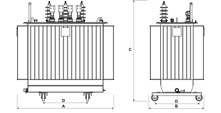
Design
The designs are made with the programs we have developed in-house with our own license and experienced technical staff. With reference to customer demands, the project team meticulously follows up from the proposal stage to the order and delivery stage. Every stage of design and implementation is approved by the customer.
The meticulous and realistic work at the proposal stage eliminates returns in production or design. Our design team gets all the information about the working place and conditions and guides the customer not to make wrong choices.
The meticulous and realistic work at the proposal stage eliminates returns in production or design. Our design team gets all the information about the working place and conditions and guides the customer not to make wrong choices.
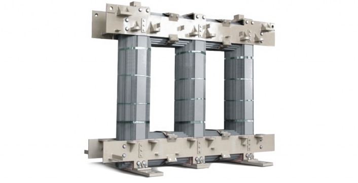
Core
The core as a magnetic circuit element is manufactured from high quality, oriented, cold rolled, low loss, insulated silicon steel sheets on both sides. According to the design inputs, the project is made using sheets of 0.23 - 0.27 - 0.30 mm thickness and with various properties. It is cut and aligned according to the technical details of the project and turned into a magnetic circuit. The parts that carry the winding in the core are called legs, and the parts that connect the legs from the top and bottom are called yokes. Vibrations are eliminated by clamping the yoke part with a metal component.
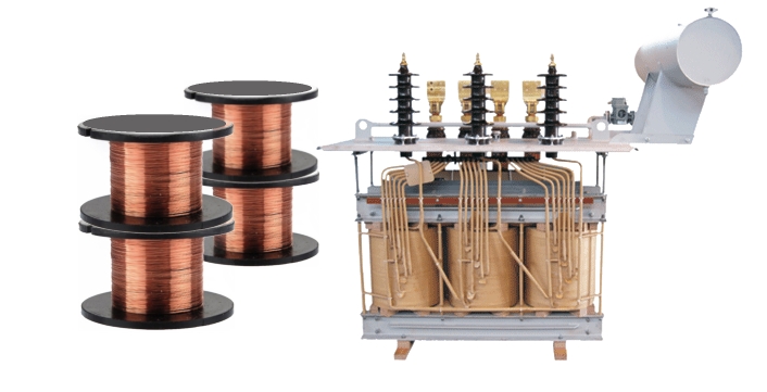
Windings
There are two main parts in distribution transformers. These are Low Voltage (LV) winding and High Voltage (HV) winding. Since the LV winding voltage is low and current is high, high cross-section conductors are generally used for insulation purposes, close to the core, that is, it is wound inside. Since the HV winding has high voltage and low current, it is generally wound on the LV coil, that is, outside, by using smaller cross-section conductors. Selections are made from electrolyte copper and aluminum materials with high conductivity and purity. As insulation, insulation materials with increased density, very high insulation levels, mechanical strength, oil resistant and of European origin are used. Coil losses, overload resistance and cooling calculations are designed and windings are made according to the project.
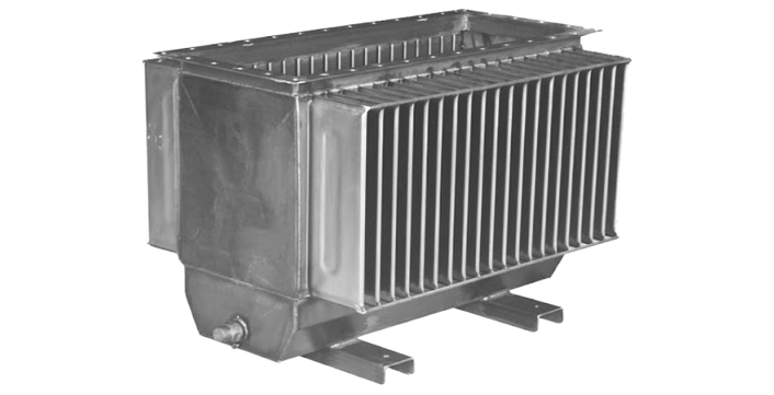
Cover – Boiler
Transformer covers are made of high quality st-37, st-52 steel materials. In accordance with the project, terminal outputs and protection are manufactured by mounting the expansion tank mounting point and lifting ears, if there is monitoring equipment. Depending on the magnitude of the current passing through the terminals, it is reinforced with antimagnetic sheet so that the phase-to-phase and/or phase-neutral current loop does not overheat the cover sheet. Cover welds are made with leakproof welding technique and are sent to assembly after leak checks are made.
The transformer boiler is manufactured from high quality st-37, st-52, and radiator or elastic wave wall sheets as cooling group. Wave wall and/or radiator sheets are used as 102 mm or 1.5 mm. All equipment is assembled in accordance with the project. Boiler welds are made with a very special impermeable welding technique, due to the welding of thin sheet to thick sheet. After the production of the boiler, the penetrating liquid is squeezed, pressure is applied, and after the leak checks are made in a dark environment with black light, it is shipped to the assembly.
The transformer boiler is manufactured from high quality st-37, st-52, and radiator or elastic wave wall sheets as cooling group. Wave wall and/or radiator sheets are used as 102 mm or 1.5 mm. All equipment is assembled in accordance with the project. Boiler welds are made with a very special impermeable welding technique, due to the welding of thin sheet to thick sheet. After the production of the boiler, the penetrating liquid is squeezed, pressure is applied, and after the leak checks are made in a dark environment with black light, it is shipped to the assembly.
Installation
The coils are threaded onto the core legs. After the core yoke parts are arranged and the magnetic circuit is closed, the coils are compressed and fixed with insulation wedges, core yoke irons, and are compressed and fixed in such a way as to resist the calculated short-circuit forces. The core is physically mounted on the cover and the coils as conductive terminal outputs and the active part is formed. After the insulation distances to the boiler are tested before or after the drying processes of the active part according to the process, assembly operations are carried out and sent to the oil pumping procedure.
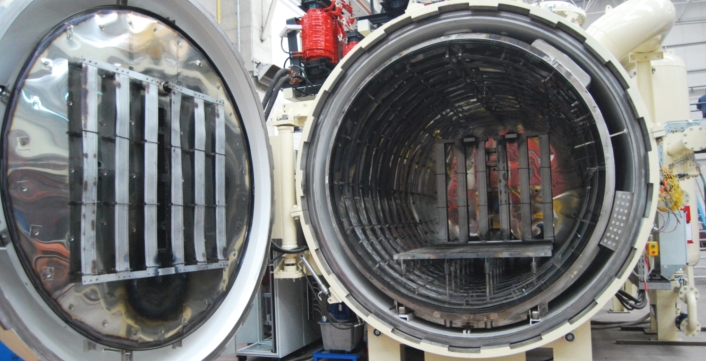
Oven and Oil Press
As it is known, it is very important to dehumidify the transformer for its insulation life and therefore its operating life. Transformers, whose active part assembly is completed, are kiln-dried at 105-110 degrees temperature, in furnaces that can reach high vacuum levels with equal heat distribution, and their moisture is removed. Baking is kept under control by making insulation measurements at the beginning and end of the baking process.
Oil pumping is carried out under high vacuum to transformers that are ovend and boiler mounted. Generally, dehumidified mineral oils are used, which are strengthened in terms of insulation and temperature resistance. In addition, special vegetable or non-combustible oils can also be used.
The process is completed by making oil level adjustments of transformers with expansion tanks and special pressure adjustments of hermetic transformers.

